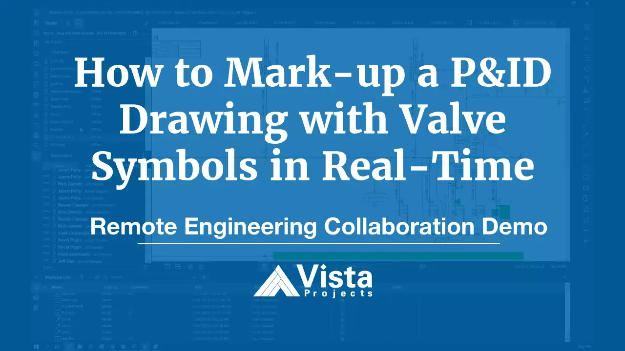
In this remote engineering collaboration demo video, Scott Mussbacher, System Integration Lead with Vista Projects, shows how to mark-up a P&ID drawing with valve symbols in real-time.
How to Mark-up a P&ID Drawing with Valve Symbols in Real-Time
Hi, I’m Scott Mussbacher from Vista Projects.
Let me show you how we’ve been doing online squad checks and stick file management for the last seven years.
This method is based on the lessons we’ve learned from our digital project execution strategies that we’ve developed as we’ve really moved into the digital age.
Let me show you.
As you can, see we’ve got a P&ID stick file where we’ve got multiple different stakeholders, including:
- process engineers
- designers
- mechanical engineers
- project managers, as well as
- our clients
It’s critical that they all have immediate access to real-time information.
And that’s exactly what we’ve set up here.
To make changes, let me show you how easy it is.
For example, I’d like to change this 2-inch gate valve into an alternate valve style.
To do that, I can go to Vista’s pre-defined toolset, and select this valve.
- I go in…
- make it larger…
- set the background to white…
- flip it into the correct orientation…
- place it there…
- and delete the other valve.
As you can see, it was really easy to do and I am left with a very professional-looking
P&ID mark-up that’s clear to everyone what’s going on.
In addition, every single contributor and stakeholder of this P&ID stick file can see this information put up here now.
In addition, this stick file also records exactly when I made these changes.
So you can understand perfectly when things were changed, and filter and change as required.
This process is much more simple than a paper version where you use to need to keep track of multiple different logs and files.
And it allows everyone to access this from the comforts of their office, their home, or other remote location.
So not only can we, here at Vista, work remotely but by executing our projects digitally, we are also much more efficient than traditional methods.
If you need help collaborating with your teams, or want to learn more about how we found our success, feel free to reach out.
Or leave us your questions below.
Have a great day.
FAQ – P&ID Collaboaration
What does P&ID stand for?
P&ID is the abbreviation for piping and instrumentation drawing.
A P&ID is a two-dimensional (2D) diagram that contains the engineering details about a design’s piping and instrumentation components. A P&ID includes information about the following:
- instrumentation engineering designations
- names and numbers of mechanical equipment
- all types of valves and associated symbols
- process piping sizes and IDs
- vents, drains, special fittings, sampling lines, reducers, expanders, and swagger
- flow directions
- interconnection references
- control system inputs, interlocks, and output functions
- class change interfaces
- all process components and subsystems
What is the best software for P&ID markups?
This remote collaboration demo video highlights Vista’s use of Bluebeam Revu for P&ID markups during online engineering squad checks.
This video shows how easy it is to markup a piping and instrumentation diagram (P&ID or sometimes called a P&ID diagram) stick file with P&ID valve symbols in Bluebeam Revu. The main advantages include:
- real-time, simultaneous access to the file
- automated mark-up and comment tracking logs
- professional, clean mark-ups and changes to P&ID symbols for ease-of-use
- accessible from anywhere with an internet connection
Online squad checks are a core component of Vista’s truth-based industrial engineering.
How do P&ID drawings work with a single-source-of-truth (SSOT)?
P&ID Drawings and Truth-Based Engineering
Our unique approach to digital project executionDigital project execution (DPE) is a project management methodology that uses a data-centric approach to reduce project total-install-cost a... uses an authoritative, single-source-of-truth environment to ensure all stakeholders have on-demand access to accurate and verifiable data. This data-centricA data-centric outlook is a core concept in digital project execution architecture where data is viewed as the most important and perpetual ... industrial engineering model has many benefits, including:
- improved transparency
- greater collaboration
- higher quality
How does a single-source-of-truth (SSOT) environment work with P&ID drawings?
As you see in the demo video above, all stakeholders can simultaneously add comments and change instrument symbols in the diagram software.
This functionality is enabled by the SSOT environment, where everyone works on the same file in real-time. It doesn’t matter if the user is adding a ball valve to a P&ID or updating a process flow diagram. With our truth-based execution model, all actions are logged and easily audited.
It’s not difficult to understand how this digital workflowThe digital workflow involves the use of digital tools instead of paper-based manual systems to perform the tasks that comprise a business w... saves time when working on a single file. When applied across hundreds of files on a large-scale industrial asset, the efficiencies add up to significant cost savings.
Engineering Consultation
Get expert help configuring your engineering operations, project, or asset for remote collaboration.


